Frequency Counter:
Frequency Counter or Frequency Meter is a digital instrument that measures the frequency of any periodic waveform. It has high sensitivity, resolution, accuracy, and stability. It can perform a wide range of functions such as frequency, measurement, period measurement, the ratio of frequencies measurement, scaling, time interval measurement, etc.
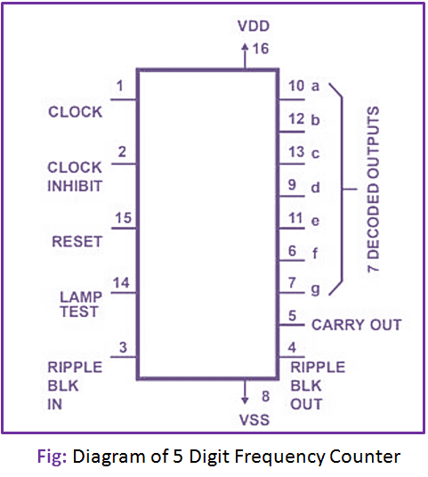
5 Digit Frequency Counter:
The logic diagram of 5 Digit Frequency Counter is shown below:
Here the kHz oscillator signal is divided into 100 Hz, 1 Hz, and 0.1 Hz time base signals using a 4-stage frequency divider. Any of these time base signals are selected with the help of a rotary selector switch and connected to the clock input of a JK flip-flop. The JK flip-flop divides the frequency of the time base signal by a factor of 2 so that the ON time of ENABLE signal is equal to the period of the respective time base signal.
When the ENABLE signal is HIGH, the unknown input signal is passed through the AND gate and acts as CLOCK input of the 5-stage counter, and thereby the counter advances its value. When the ENABLE signal becomes LOW, the counter ceases its operation. Simultaneously, a low to high transition at Q’ strobes or latches the counter contents in the display latches.
Also, the high-to-low transition at Q output triggers the one-shot mono-stable multi-vibrator. Its output resets the content of the 5-stage counter to 00000 and it gets ready for another cycle of frequency measurement. Now, the value displayed in the 5-digit 7-segment display is proportional to the frequency of the unknown input signal.