Microprocessor-based system:
The microprocessor is a semiconductor device (Integrated Circuit) manufactured by the VLSI (Very Large Scale Integration) technique. It includes the ALU, register arrays, and control circuit on a single chip. A system designed using a microprocessor as its CPU is called a microcomputer or single-board microcomputer. The microprocessor based system consists of the microprocessor as CPU, semiconductor memories like EPROM and RAM, input device, output device, and interfacing devices. The memories, input devices, output devices, and interfacing devices are called peripherals.
Block Diagram of Microprocessor:
The popular input devices are keyboards, floppy disks, etc., and the output devices are printers, LED/LCD displays, CRT monitors, etc. The block diagram of the microprocessor based system is given below:
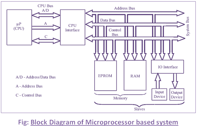
In this system, the microprocessor is the master and all other peripherals are slaves. The master controls all the peripherals and initiates all operations. The buses are groups of lines that carry data, addresses, or control signals. The CPU bus has multiplexed lines, the same line is used to carry different signals. The CPU interface is provided to de-multiplex the multiplexed lines, to generate chip-select signals and additional control signals. The system bus has separate lines for each signal.
All the slaves in the system are connected to the same system bus. At any time instant communication takes place between the master and one of the slaves. All the slaves have tri-state logic and hence normally remain in a high impedance state. The processor selects a slave by sending an address. When a slave is selected, it comes to the normal logic and communicates with the processor.
The EPROM memory is used to store permanent programs and data. The RAM memory is used to store temporary programs and data. The input device is used to enter the program, and data and to operate the system. The output device is also used for examining the results. Since the speed of IO devices does not match the speed of the microprocessor, an interface device is provided between the system bus and IO devices. Generally, IO devices are slow devices.
The work done by the processor can be classified into the following three groups:
1. Work done internally to the processor.
2. Work done external to the processor.
3. Operations initiated by the slaves or peripherals.