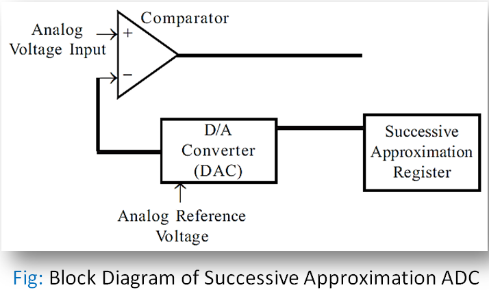
Block Diagram of Successive Approximation ADC:
A successive approximation ADC consists of a D/A converter, successive approximation register, and comparator. The figure shows the functional blocks of a typical successive approximation A/D converter.

The conversion process is initiated by a Start Of Conversion (SOC) signal from the processor to ADC. On receiving the SOC, the control unit of ADC will give a start command to the successive approximation register and it starts generating a digital signal by the successive approximation method. The generated digital data is converted to an analog signal by a D/A converter and then compared with the given analog signal. When the analog signals are equal the comparator output informs the control unit to stop the generation of the digital signal. The digital data available at this instant are given as output through the output register. Also, the control unit generates a signal to indicate the End Of the Conversion (EOC) process to the processor.