Multiplexed Display:
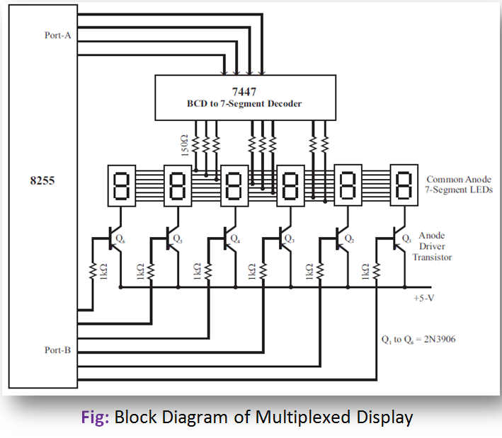
In multiplexed display, only one 7-segment display is made to glow at a time. Each 7-segment LED is turned ON at definite intervals. Due to the persistence of vision, the display appears to be continuous to the human eye. The segment pins (cathodes) of 7-segment LEDs are connected to a common bus. The output of the decoder (7447) is connected to this common bus. The BCD code for the character to be displayed is sent to 7447 through port-A lines.
The common anode of each 7-segment LED has a driver transistor (PNP type). A driver transistor can be turned ON by sending low to the base of the transistor through port-B lines. The trick of the multiplexed display is that the segment information is sent out to all of the digits on the common bus, but only one display digit is turned on at a time. The PNP transistors in series with the common anode of each digit act as an ON and OFF switch for that digit.
Next, the BCD code for digit-2 is output to the 7447 on port-A, and data to turn ON the driver transistor of digit-2 is output on port-B. After a few milliseconds, digit-2 is turned OFF and the process is repeated for digit-3. This process is continued until all of the digits have had a turn. Then digit-1 and the following digits are turned ON again in turn.
This process is also called display refreshing. With 6 digits and 5 ms per digit, we can get back to digit-1 every 25 ms or about 40 times a second. This refresh rate is fast enough so that, all digits appear to be turned ON all the time. Refresh rates of 40 to 200 times a second are acceptable.