8257 DMA Controller:
The DMA controller-8257 has been developed for 8085/8086/8088 the microprocessor-based system. It is a device dedicated to performing a high-speed data transfer between memory and IO device. The 8257 has four channels. So, it can be used to provide DMA to four IO devices. It cannot be connected in a cascade-like 8237 and it has fewer features than 8237.
For each DMA channel, an address register and a count register has been dedicated to storing the memory address and the count value for a number of bytes to be read/written by DMA respectively. Apart from these dedicated registers, the 8257 has a mode set and status registers.
Features of 8257 DMA Controller:
i. It has four independent DMA channels to service four IO devices.
ii. Each channel can be independently programmable to transfer up to 64 kb of data by DMA.
iii. Each channel can independently perform read transfer, write transfer, and verify the transfer.
Block Diagram of 8257:
The functional block diagram of 8257 is shown in below Fig. The functional blocks of 8257 are data bus buffer, read/write logic, control logic, and four numbers of DMA channels.
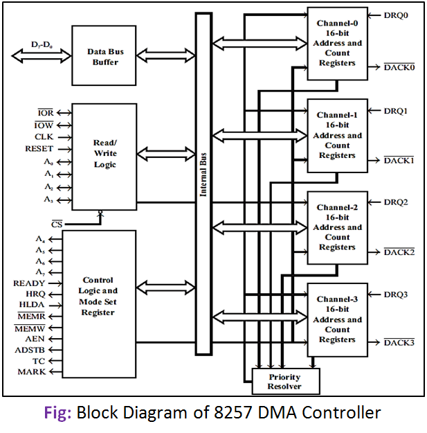
Each channel has two programmable 16-bit registers. One register is used to program the starting address of the memory location for DMA data transfer and another register is used to program a 14-bit count value and a 2-bit code for the type of DMA transfer (Read/Write/Verify transfer). The address in the address register is automatically incremented after every read/write/verify the transfer.
In read transfer, the data is transferred from the memory to the IO device. In write transfer, the data is transferred from the IO device to memory. Verification operations generate the DMA addresses without generating the DMA memory and IO control signals.