Motorola 6800:
The Motorola 6800 product family was originally introduced in 1974. The 6800 microprocessor CPU is manufactured in NMOS technology on a 40-pin chip, has TTL compatible pins and it is the first 8-bit single-chip microprocessor to exploit a single 5-V power supply. The 6800 CPU can drive from seven to ten 6800 family devices without buffering. A two-phase external clock (1MHz, maximum) must be externally supplied.
The 6800 CPU has three buses to communicate with the other system modules, they are data, address, and control buses. The data bus is bidirectional and has 8 lines, D0-D7. The address bus has 16 lines, A0-A15. The processor operates on 8-bit data and uses a 16-bit address for memory and IO devices.
The microprocessor does not distinguish between memory and peripheral addresses. Therefore some of the 64 k addresses must be reserved for peripheral addresses. The control bus carries two types of signals called Control bus signals and CPU (microprocessor) supervisory signals.
The HALT pin is used for DMA data transfer in block transfer mode or cycle stealing mode. When HALT is asserted low, the microprocessor halts all its activity at the completion of the current instruction.
The Tristate Control (TSC) may be used to implement DMA on a cycle stealing basis. If TSC is placed in a high state, the address bus and the R/W line get a high impedance state 500 ns later. The data bus is not affected by TSC and has its own enable (DBE). This approach assures rapid response to the DMA request. Since the internal memory of the 6800 is dynamic, however, the TSC terminal cannot be held in a high state for longer than 5 μs if loss of data in the microprocessor is to be avoided.
Architecture of Motorola 6800:
The architecture of Motorola 6800 includes the ALU, 16-bit Program Counter (PC), 16-bit stack pointer, 16-bit index or general purpose register, two 8-bit accumulators, and a condition code register. The stack pointer allows a LIFO (Last-In-First-Out) stack to be implemented at any address in memory and to be limited in size only by the memory space.
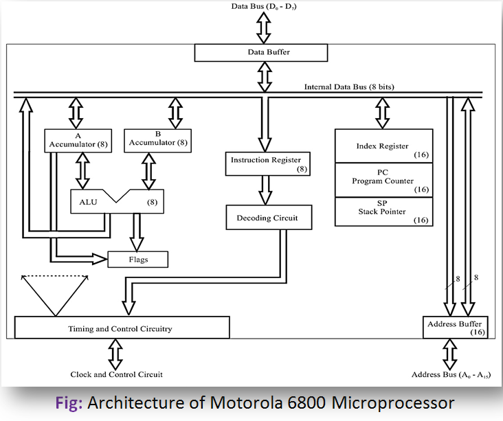
The index register may be used to store data or a 16-bit memory address for use in the indexed mode of addressing. The Condition Code Register (CCR) indicates the results of an ALU operation. The flags in CCR are Negative (N), Zero (Z), Overflow (O), Carry(C), Half carry (H), and Interrupt enable/disable (I). The unused bits of the CCR are 1’s.
The ALU performs arithmetic and logical operations including AND, OR, EXCLUSIVE-OR, NEGATE, COMPARE, ADD, SUBTRACT, and DECIMAL ADJUST which allows BCD arithmetic to be performed. Immediate, direct, indexed, and relative addressing modes are used in 6800.