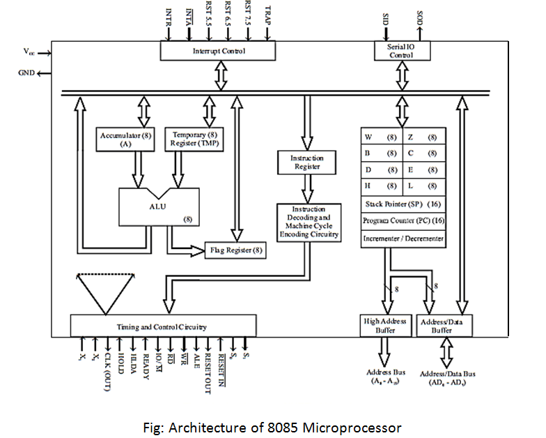
Architecture of 8085:
The 8085 includes the ALU, timing and control unit, instruction register and decoder, register array, interrupt control and serial IO control. The ALU performs arithmetic and logical operations. The operations performed by ALU of 8085 are addition, subtraction, increment, decrement, logical AND, OR, EXCLUSIVE-OR, compare, complement and left /right shift. The accumulator and temporary register are used to hold the data during an arithmetic/ logical operation. After an operation, the result is stored in the accumulator and the flags are set or reset according to the result of the operation. The accumulator and flag register together are called Program Status Word (PSW).
There are five flags in 8085, they are Sign Flag (SF), Zero Flag (ZF), Auxiliary Carry Flag (AF), Parity Flag (PF) and Carry Flag (CF). The bit positions are reserved for these flags in the flag register. After an ALU operation, if the most significant bit of the result is 1, the sign flag is set. The zero flags are set if the ALU operation results in zero and it is reset if the result is nonzero. In an arithmetic operation, when a carry is generated by the lower nibble, the auxiliary carry flag is set. After an arithmetic or logical operation if the result has an even number of 1’s the parity flag is set, otherwise, it is reset.
If an arithmetic operation results in a carry, the carry flag is set, otherwise, it is reset. Among the five flags, the AF Flag is used internally for BCD arithmetic and the other four flags can be used by the programmer to check the conditions of the result of an operation.