Microcomputer with DMA Controller:
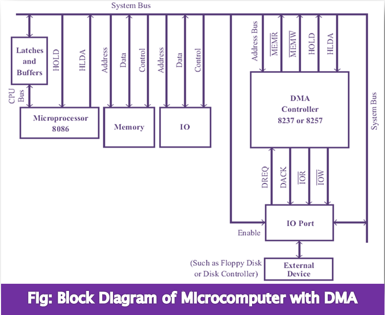
In the system, the DMA controller has one channel, which serves as one IO device. In an actual DMA controller we may have more than one channel and each channel may service an IO device independently. Each channel contains an address register, a control register, and a count register. For the sake of simplicity let us consider one channel DMA controller. The block diagram of a microcomputer system with a DMA controller is shown in fig.
The DMA controller can work as a slave or as a master. In the slave mode, the microprocessor loads the address register with starting address of the memory, loads the count register with the number of bytes to be transferred, and loads the control register with control information.
For performing DMA operation the processor has to initialize or program the IO device and DMA controller. Consider an example of transferring bulk data from floppy to memory by DMA. In this case, the processor initializes both the DMA controller and the floppy controller, so that the DMA controller is informed about the address, type of DMA and the number of bytes to be transferred, and the floppy controller is informed to go for a DMA.
When the IO device needs a DMA transfer it sends a DMA request signal (DREQ) to the DMA controller. When the DMA controller receives a DMA request, it sends a HOLD request to the processor. At the end of the current instruction execution, the processor relieves the bus by asserting all its data, address and control pins to high impedance state. Then the processor sends an acknowledge (HLDA) signal to the DMA controller.